The first is what I have dubbed the GTN V2 encoder (the GTN V1 encoder encountered a few problems and was abandoned, but more on that later). I had been trying to squeeze as much onto a 40mmx40mm encoder board as possible (the same size as a Pro Mini Strong), but wondered what I could do with a board that was 40mmx20mm, half the size of a Pro Mini Strong. I wanted an encoder of similar performance and features of my range of encoders with an LCD, ie multi-model memory and most common computer transmitter features. I got to work with KiCAD and this is what I came up with with the computer-generated 3D image:
It uses an ATmega328PB-MU, a tiny 0.42" OLED, three programming switches, a diminutive sounder that only measures 5mmx5mm but is as load as the typical 12mm round sounders often used, a pot and zener diode for a full-scale-range meter and most of the connections via a 12-way JST-XH connector with a pre-wired plug with 20cm cable tails. This was ordered with JLCPCB and these arrived through the post:
I then assembled a few of them with different height tactile switches to see what height worked best. In production versions, I will use SMD tactile switches assembled at the factory to save me some soldering and cost.
So you can judge its size, here are two of them with a Pro Mini Strong.
Even though the OLED is tiny, it is very easy to read under normal lighting (but the same as any other OLED, not so good in direct sunlight).
The hardware specification is as follows:
● Compact 40mm x 20mm.
● 6.6V - 9.6V operation with reverse polarity protection.
● 0.42” OLED display with 10 characters x 3 rows of text (72x40 resolution ).
● The joysticks, auxiliary channels and switches are wired via a 12-way JST ZH connector with a 12-way plug with 20cm of cable pre-wired.
● Power in, PPM output and the meter are all standard 0.1" headers.
● On-board multi-tone alarm sounder.
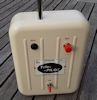
● On-board Zener diode/potentiometer to re-use the original meter for an expanded scale battery indication .
And the firmware:
● 10 Model Memory.
● 9-character model names
● 8-Channels, Aileron left and right, Elevator, Rudder, Throttle, Aux1, Aux2 and Gear.
● Servo-reverse on all channels.
● End-point adjust on all channels (also called travel volume, servo travel adjust etc).
● Sub-trim on all channels.
● Trim on A, E and R with "Auto Trim" on a push switch
● Dual Rates/Expo on ailerons, elevator and rudder.
● Freely assignable channel output order
● Elevon and V-Tail mixing with adjustable mixing ratio.
● Aileron differential (user adjustable).
● Aileron to rudder mix, often called CAR (coupled ailerons/rudder).
● Knife edge compensation mix (rudder to aileron and rudder to elevator).
● Throttle to elevator/rudder/aileron mix (to allow for incorrect thrust line).
● Flap to elevator mix (to stop zooming when the flaps are lowered).
● Crow brake (also called butterfly) which raises aileron when flaps are dropped.
● Count-down timer controlled via throttle position or gear switch.
● Throttle cut (via the throttle cut switch).
● Power on “soft throttle lock”.
● Low voltage alarm (user adjustable alarm voltage).
● “Trim Alarm” if trims not centred when powering up or new model memory selected
● Inactivity alarm.
● JR or Futaba PPM "polarity" and channel order
If I have enough memory spare I will add free mixers, but I still have a bit more programming to do,
I have most finished with just a few of the mix functions still to complete, I can "borrow" the code from my LCD encoders for most, but I need to re-work the menus. Here it is connected to a ppm meter.
And the connections:

 Please put me down for a GTN V2 as and when it becomes available......